Objective: To configure port-channel and associate it to vlan.
Servers will use Cisco-NXOS as their gateway and uplink to Internet. Server-switch have Layer 2 (access mode) connectivity to Cisco-NXOS router. (see Fig.1)
Fig.1
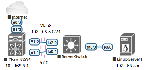
1. Configure the Vlan (interface vlan will be the server’s gateway)
Cisco-NXOS#
configure
vlan 8name Server-Farm
interface Vlan8description Server Farm Vlanno shutdownip address 192.168.8.1/24
2. Configure port-channel
interface port-channel10description Port-channel to Server-Switchswitchport access vlan 8
3. Configure physical members
interface eth1/1description Connection to Server-Switch fa0/1switchport access vlan 8channel-group 10 mode activeno shutdown
interface eth1/2description Connection to Server-Switch fa2/0switchport access vlan 8channel-group 10 mode activeno shutdown
Verification and sample output:
Server1 = 192.168.8.20
Server2 = 192.16 8.8.21
ARP:
show ip arp <vlan id>
Cisco-NXOS# show ip arp vlan8
Flags: * – Adjacencies learnt on non-active FHRP router
+ – Adjacencies synced via CFSoE
# – Adjacencies Throttled for Glean
CP – Added via L2RIB, Control plane Adjacencies
PS – Added via L2RIB, Peer Sync
RO – Re-Originated Peer Sync Entry
D – Static Adjacencies attached to down interface
IP ARP Table
Total number of entries: 2
Address Age MAC Address Interface Flags
192.168.8.20 00:15:47 0011.abcd.ef00 Vlan8
192.168.8.21 00:15:47 0011.abcd.ef01 Vlan8
Ping:
ping <IP> source <interface IP>
Cisco-NXOS# ping 192.168.8.20 source 192.168.8.1
PING 192.168.8.20 (192.168.8.20) from 192.168.8.1: 56 data bytes
64 bytes from 192.168.8.20: icmp_seq=0 ttl=63 time=0.62 ms
64 bytes from 192.168.8.20: icmp_seq=1 ttl=63 time=0.441 ms
64 bytes from 192.168.8.20: icmp_seq=2 ttl=63 time=0.454 ms
64 bytes from 192.168.8.20: icmp_seq=3 ttl=63 time=0.54 ms
64 bytes from 192.168.8.20: icmp_seq=4 ttl=63 time=0.394 ms
— 192.168.8.20 ping statistics —
5 packets transmitted, 5 packets received, 0.00% packet loss
round-trip min/avg/max = 0.394/0.489/0.62 ms
Check Port-channel:
show interface port-channel <port-channel id>
Cisco-NXOS# show int port-channel 10 | i Members
Members in this channel: Eth1/1, Eth1/2
Check Vlan:
show vlan
Cisco-NXOS# show vlan
8 Server-Farm active Po10
Verify the traffic:
show int port-channel1show int vlan8show int eth1/1show int eth1/2
For SSH Configuration in Juniper, pls. refer to this link –> Configuring Port-Channel and VLAN in Juniper
[…] Servers will use Juniper-Router as their gateway and uplink to Internet. Server-switch have Layer 2 (access mode) connectivity to Juniper-Router. (see Fig.1) Fig.1 1. Configure the Vlan (interface vlan will be the server’s gateway) Juniper-Router# configure set vlans VLAN-8 description Server-Farm set vlans VLAN-8 vlan-id 8 set vlans VLAN-8 l3-interface irb.8 set interfaces irb unit 8 description “Server Farm Vlan” set interfaces irb unit 8 family inet address 192.168.8.1/24 2. Configure port-channel set interfaces ae10 description “Port-channel to Server-Switch” set interfaces ae10 aggregated-ether-options link-speed 1g set interfaces ae10 aggregated-ether-options lacp active set interfaces ae10 unit 0 family ethernet-switching interface-mode access set interfaces ae10 unit 0 family ethernet-switching vlan members VLAN-8 3. Configure physical members set interfaces ge-0/0/0 description “Connection to Server-Switch fa1/0” set interfaces ge-0/0/0 gigether-options 802.3ad ae10 set interfaces ge-0/0/1 description “Connection to Server-Switch fa2/0” set interfaces ge-0/0/1 gigether-options 802.3ad ae10 4. Commit all changes commit Verification and sample output: Server1 = 192.168.8.20 Server2 = 192.16 8.8.21 ARP: Juniper-Router> show arp interface ae10.0 MAC Address Address Name Interface Flags 00:11:ab:cd:ef:00 192.168.8.20 192.168.8.20 ae10.0 none 00:11:ab:cd:ef:01 192.168.8.21 192.168.8.21 ae10.0 none Total entries: 2 {master} Ping: user1@Juniper-Router-re0> ping 192.168.8.20 source 192.168.8.1 count 2 PING 192.168.8.20 (192.168.8.20 ): 56 data bytes 64 bytes from 192.168.8.20 : icmp_seq=0 ttl=64 time=1.162 ms 64 bytes from 192.168.8.20 : icmp_seq=1 ttl=64 time=1.098 ms — 192.168.8.20 ping statistics — 2 packets transmitted, 2 packets received, 0% packet loss round-trip min/avg/max/stddev = 1.098/1.130/1.162/0.032 ms {master} Check Port-channel: user1@Juniper-Router-re0> show lacp interfaces ae10 Aggregated interface: ae10 LACP state: Role Exp Def Dist Col Syn Aggr Timeout Activity ge-0/0/0 Actor No No Yes Yes Yes Yes Slow Active ge-0/0/0 Partner No No Yes Yes Yes Yes Slow Active ge-0/0/1 Actor No No Yes Yes Yes Yes Slow Active ge-0/0/1 Partner No No Yes Yes Yes Yes Slow Active Check Vlan: user1@Juniper-Router-re0> show vlans VLAN-8 Routing instance VLAN name Tag Interfaces default-switch VLAN-100 100 Verify the traffic: monitor interface ae10.0 monitor interface ge-0/0/0 monitor interface ge-0/0/1 Here’s the Cisco version for this –> Configuring Port-Channel and VLAN in Cisco Nexus […]